MFA Thesis - Shot 4
MFA THESIS
12/18/20244 min read
Shot 4 - Reference

Shot 4 - Final Render and Breakdown
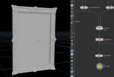
Shot 4 - High Res Still
Shot 4 - Destruction: Fracture R&D and Set up
I have been researching different methods for setting up fractures before feeding them into the RBD solver, since Shot 4 involves a small-scale destruction simulation. My goal is to experiment with RBD materials and customize the constraints between different materials to study how they interact with each other. In this shot, the setup includes a photo frame composed of wood, the photo frame’s glass element, and the picture itself, which will be simulated using Vellum.
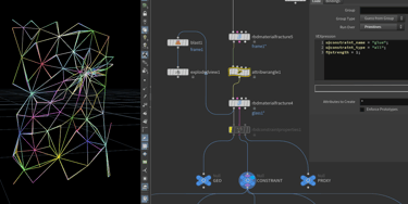
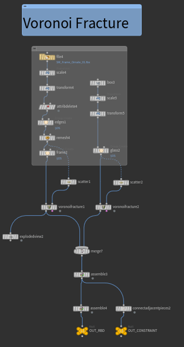
First, I set up the simulation using the traditional method with a Voronoi Fracture. This approach produces more uniform fracture pieces without particularly interesting shapes, but it is fast and offers significant flexibility for customizing both constraints and the overall shape.
Another method is to use Boolean operations (see the comparison in the Shot 5 blog). However, Boolean fracturing can be less stable, as it often introduces geometry issues that require cleanup. In contrast, Voronoi Fracture is straightforward to set up. After applying the Voronoi Fracture node, the geometry simply needs to be merged and passed through an Assemble node to generate the name attribute and pack the geometry. This packed geometry can then be connected to constraints using connectadjacentpieces. Both the geometry and the constraints can subsequently be fed into the RBD solver.
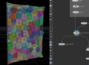
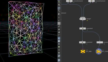
voronoi fracture
packed geo fed into RBD
constraint into RBD
1.Voronoi Fracture
2.RBD Material Fracture
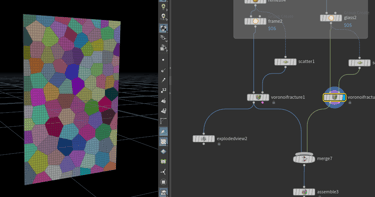
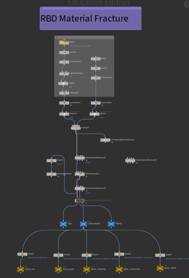
The second approach is to use RBD Material Fracture. Although this method can be quite slow to simulate, even with relatively low-resolution geometry, it produces more visually interesting fracture patterns, particularly for glass. However, one drawback is efficiency: since the node generates constraints internally, adjusting any slider values forces the entire simulation to be recomputed. This makes iteration less efficient compared to Voronoi Fracture. Even if constraints are disabled, the node still runs the constraint simulation process and does not generate the necessary name attributes.
To set up this method, the workflow requires assembling the different materials separately before merging them and feeding them into the RBD Material Fracture node. Each material must be assigned a specific name attribute during the assembly stage. Afterward, connectadjacentpieces is used to link nearby pieces, ensuring interaction between materials. Inside the RBD Material Fracture node, groups can be assigned and the material type selected. One notable feature is that the Concrete material type allows multiple layers of fracture levels, which is highly useful in certain scenarios; however, this option is not applicable in the current shot since no concrete is present.
Finally, the primary attributes used to control the simulation are s@constraint_name, s@constraint_type, and f@strength. These attributes define the constraints between pieces and their behavior during the simulation.
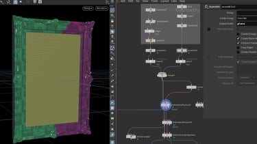
RBD Material Fracture - Wood
RBD Material Fracture - Glass
Assemble before feed into
set up Attribute for Constraint
Different constraints computed by RBD Material Fracture
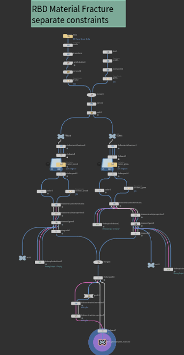
3.RBD Material Fracture + Separate constraints set up
Faster Simulation / separated controls of constraints
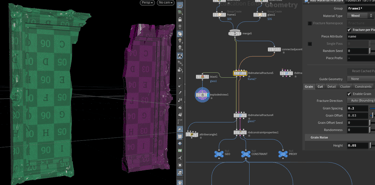
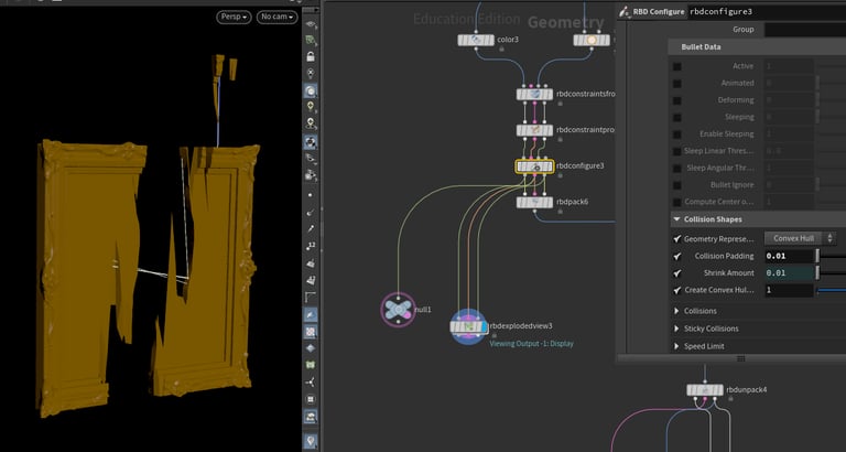
Since the first method was too slow and any adjustment to a single value required the entire simulation to be recomputed, taking considerable time. I modified the workflow by separating the different materials before feeding them into the RBD Material Fracture node and then packing the geometry after the simulation. For the constraints, I assigned higher grain strength values to the wood in order to keep it from breaking excessively, and lower values for the glass to allow more realistic shattering.
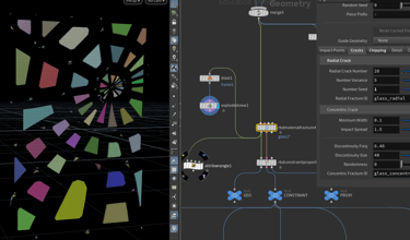
Next, I used rbdconstraintsfromrules4, which enables the creation and editing of constraints based on specific rules and conditions, followed by rbdconstraintproperties4 to generate attributes on the input constraints. After that, I applied rbdconfigure, which allows properties to be set individually for different RBD object groups. This provided control over collision shapes, padding, and the overall performance of the pieces as they dropped to the ground.
Once the constraints were configured separately, I merged the geometries back together to establish constraints between different materials. After the merge, I unpacked the geometry and used rbdconstraintsfromrules and rbdconstraintproperties again to refine constraint behavior. In rbdconstraintsfromrules5, constraint groups were defined by assigning group names, which could then be managed and fine-tuned in rbdconstraintproperties5.
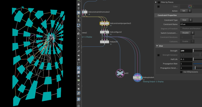
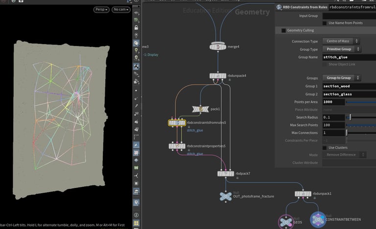
Wood Constraint
Glass Constraint
Constraint between Wood and Glass
Shot 4 - Destruction: RBD Sim / deform with animation
After completing the fracture and constraint setup, I used an Object Merge to bring the geometry into another SOP network. A Null node was then connected at the top level to serve as the starting point for the geometry. This approach provides flexibility, as the starting point can be easily adjusted or replaced, and the SOP network can be repositioned directly from the Null.
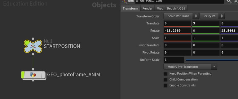
For the RBD simulation, the fractured and constrained geometry was moved to the defined starting point and then fed into a DOP Network with an RBD Solver. After the simulation, I imported only the points to improve efficiency and used Transform Pieces to map the original geometry onto the simulated points. Finally, I applied Point Deform to transfer the high-resolution geometry onto the simulated geometry, while also extracting point velocity data to generate accurate motion blur.
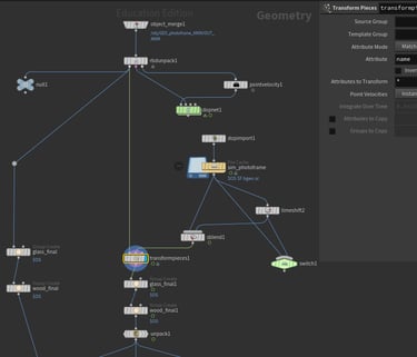
Dop Import
Transform Pieces
Point Deform
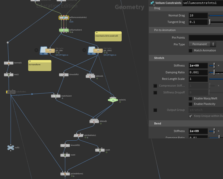
Shot 4 - Vellum sim for picture
For this setup, I used Vellum and set the photo frame as the collision object. The challenge I encountered was positioning the picture between the glass and the frame. At the start of the simulation, this caused unexpected stretching artifacts because the photo geometry was too close to the frame. To address this, I created two separate simulations: in the first, I slightly moved the photo forward to avoid direct interaction with the frame; in the second, I placed the photo correctly between the glass and the wooden frame. I then used a time blend between the two simulations to achieve a smooth transition.
Shot 4 - Particles for Embers
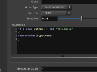
For the embers generated from the fire, my goal was to achieve a more realistic movement. To accomplish this, I animated the source using a sine function and applied a mountain node to introduce additional variation. This setup was then fed into the POP Network, where I used POP Wind to control the direction of the particles. Finally, I applied a removepoint function within an attribute wrangle to randomly delete points after the simulation, creating a more natural result.
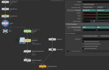
pop source
delete points randomly